


Clicking on the screen shots will expand them to full size.
Custom Peripherals
This HowTo introduces creating a custom peripheral for use in EDK projects. The peripheral is created using an EDK wizard. If you want to try manually creating a peripheral, see the Direct OPB interfacing HowTo.
Note: This HowTo uses Xilinx ISE & EDK version 9.1i
The Create and Import Peripheral Wizard
The Create and Import Peripheral Wizard provides a simple way of setting up
an interface between your custom peripheral logic and the microprocessor. The
procedure outlined in the next section will create a custom peripheral called
test_core that connects to the system's OPB bus via an IPIF
block.
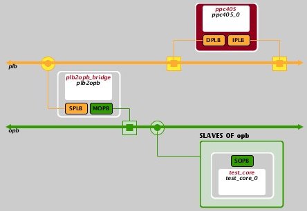
System Schematic |
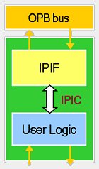
IPIF Connectivity |
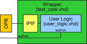
The left-hand diagrams above show the final connectivity (note that other blocks have been removed for clarity). The test_core is connected to the PPC microprocessor via two buses, the PLB (orange) and the OPB (green).
The right hand image shows the construction of the test_core custom peripheral (green). The peripheral contains two main parts, the IPIF and User Logic. The IP Interface (IPIF) (yellow) is used to glue your logic (blue) to the bus (orange). Essentially, the wizard is used to create the test_core wrapper and to insert and customise the IPIF section. It is then up to you to fill in the User Logic section.
The document opb_ipif_arch.pdf, found within the EDK installation's
doc folder, provides more information on the the OPB based IPIF
architecture.
Running the Wizard
The project from Simple Project HowTo is used as the starting point for this HowTo.
Stage 1
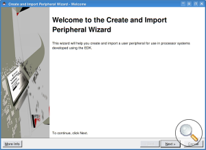
The Create and Import Peripheral Wizard can be started by selecting Hardware->Create or Import Peripheral...
Stage 2
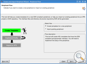
Select Create templates for a new peripheral.
Stage 3
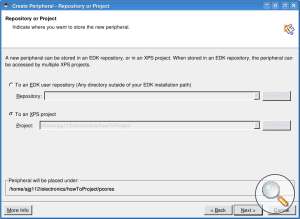
You have the option to add your new peripheral to a global repository, or to store it within the project. Select this latter option.
Once you developed your peripheral you can easily copy it to a more globally available location.
Stage 4
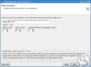
Give your new peripheral a name. For this HowTo, we'll use test_core. Note that the name is unfortunately limited to all lowercase letters.
Stage 5
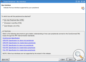
You are given various options for the type of bus you'll use to connect your peripheral to the processor. The IBM CoreConnect FAQ provides the following info:
 The prime goal of PLB is to provide a high-bandwidth, low-latency connection
between bus agents that are the main producers and consumers of the bus
transaction traffic. The prime goal of OPB is to provide for a flexible
connection path to peripherals and memory of various bus widths and transaction
timing requirements while providing minimal performance impact to the PLB bus.
The prime goal of PLB is to provide a high-bandwidth, low-latency connection
between bus agents that are the main producers and consumers of the bus
transaction traffic. The prime goal of OPB is to provide for a flexible
connection path to peripherals and memory of various bus widths and transaction
timing requirements while providing minimal performance impact to the PLB bus.

Note: If you are intending to use your peripheral with the MicroBlaze processor, you're better off choosing the OPB.
Select the OPB bus.
Stage 6
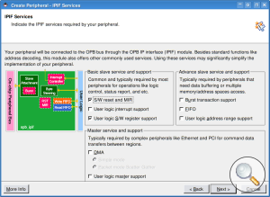
The IPIF has a number of built-in functions to make connecting your peripheral easier. Select the following options:
S/W reset and MIR - Software controlled reset and Module Information Register. A special memory location will be created, when written to it causes the reset signal to be asserted.
User logic S/W register support - Software accessible registers.
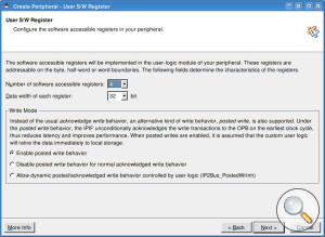
Stage 7
Next, you must select the number and width of the registers. Choose 4 32 bit wide registers.
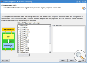
Stage 8
This section provides the opportunity to include bus signals other than those required by your settings so far. Just click next.
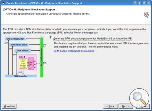
Stage 9
Click next.
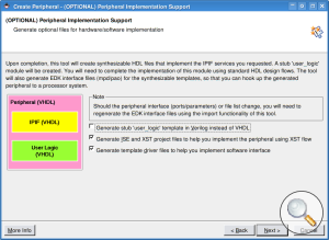
Stage 10
Click next.
Stage 11
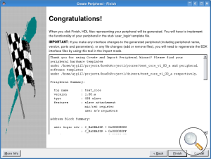
The final page gives you a summary of your peripherals settings.
You have now created the basic outline of your custom peripheral. Go on to the next section to find out how to complete the peripheral.
Writing the Peripheral VHDL
This section will describe how to create a simple peripheral that connects
to some external LEDs. As described in the previous section the Create and
Import Peripheral Wizard only creates a wrapper which needs filling with
your design. The main file that need attention is the user_logic.vhd
file.
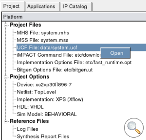
The file structure shown below shows where this file can be found.
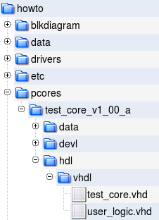
Location of the user logic file
Open the user_logic.vhd file. You will see that the wizard will
have created a template. It contains 4 registers that can be written to and
read from. Below is a link to a tidied up and a more readable version. Download
it, have a read through and replace the old version.
This version does essentially the same thing, but with a few tweaks.
Firstly, the direction of the data bus is changed. The OPB uses (0 to
31) std_logic vectors. This is the opposite to everything I'm used to (and most other VHDL designs), so I've
put in a function to reverse it.
data_BUS2IP <= reverseVector(Bus2IP_Data);
IP2Bus_Data <= reverseVector(data_IP2BUS);
I've also added in a connection between register 0 and an external LED port.
ledPort <= reg0(3 downto 0);
Connecting signals in the wrapper
As described in the introduction the user_logic.vhdl is surrounded by a
wrapper (for this peripheral this will have been created as test_core.vhd).
Because we've added some extra signals (ledPort) coming out of our user_logic block,
these need to be connected through and out of the wrapper.
The diagram below illustrates how the ledPort signals need to be added to the wrapper.
External LED Port connection
Use the link below to download the modified test_core.vhd file.
Look at the differences and then replace the old version with the new one. The
wrapper VHDL file is clearly marked with the locations where additional signals
and generics can be added if necessary.
Adding External IO
You need to make the EDK tools aware that we've added some signals (the LED Port) that we want to connect externally to the FPGA. This is done in the
MPD (Microprocessor Peripheral Description) file.
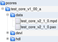
MPD file
Open the file and add the ledPort line as shown below, or download the file using the following link:
pcores/test_core_v1_00_a/data/test_core_v2_1_0.mpd
## Ports
PORT ledPort = "", DIR = O, VEC = [3:0]
PORT OPB_Clk = "", DIR = I, SIGIS = Clk, BUS = SOPB
PORT OPB_Rst = OPB_Rst, DIR = I, SIGIS = Rst, BUS = SOPB
PORT Sl_DBus = Sl_DBus, DIR = O, VEC = [0:(C_OPB_DWIDTH-1)], BUS = SOPB
Note: The version number after the MPD filename (v2_1_0) does NOT reflect the version of the peripheral. It is the version of the MPD file format.
Files
You can download the completed test_core using the link below.
Adding the peripheral
The final stage is to add the peripheral to your project.
Stage 1
First, make XPS rescan the available peripherals. Select Project->Rescan User Repositories.
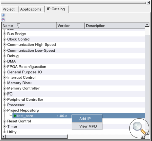
Stage 2
To add the new peripheral, find test_core under Project
Repository, or Project Local pcores. Right click and select
Add IP.
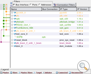
Stage 3
To connect the new peripheral to the bus, first expand the test_core instance, then click the empty green circle so that it turns filled. This shows the IP is connected.
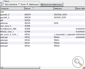
Stage 4
Select 'Addresses' in the Filters section. Then click the
Generate Addresses button. This will memory map the new peripheral
into the processor's memory space.
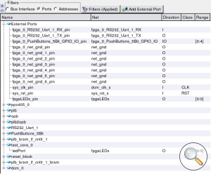
Stage 5
Now we shall connect the LEDs to an external port. Select Ports in the Filters section. Expand External Ports. This will
already contain a bunch of external signals.
- Select
Add External Port. Change the new port fromExternalPort_0tofpgaLEDs_pins. - In the next column along, add a new net name,
fpgaLEDs. - Set the direction to
Ofor output. - Change the range to [3:0] to reflect that this is a 4 bit bus.
- Finally expand the test_core and select the Net as
fpgaLEDs.
Stage 6
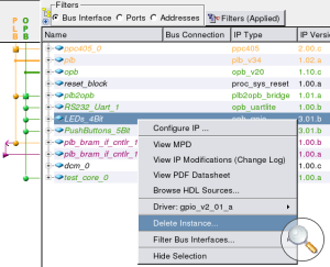
If you used the system from the Simple Project HowTo you will already have a GPIO peripheral connected to the LEDs. We will need to remove this peripheral as we can't have two peripherals driving the LEDs.
You will be prompted to choose what to do with the ports associated with the peripheral. Choose to remove both the internal and external ports.
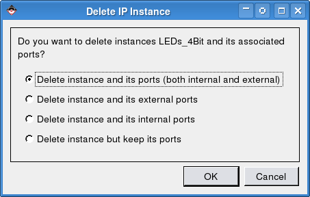
GPIO Disconnect Dialog
Stage 7
The last stage is to edit the system's UCF (User Constraints File) and make sure that the new ledPort signals are actually connected to the FPGA pins
that are routed to the LEDs.
First open the system's UCF file.
Once opened look for the constraints for the old GPIO peripheral (shown below), these all need removing.
#### Module LEDs_4Bit constraints
Net fpga_0_LEDs_4Bit_GPIO_IO_pin<0> LOC=AC4;
Net fpga_0_LEDs_4Bit_GPIO_IO_pin<0> IOSTANDARD = LVTTL;
Net fpga_0_LEDs_4Bit_GPIO_IO_pin<0> SLEW = SLOW;
Net fpga_0_LEDs_4Bit_GPIO_IO_pin<0> DRIVE = 12;
Net fpga_0_LEDs_4Bit_GPIO_IO_pin<1> LOC=AC3;
Net fpga_0_LEDs_4Bit_GPIO_IO_pin<1> IOSTANDARD = LVTTL;
Net fpga_0_LEDs_4Bit_GPIO_IO_pin<1> SLEW = SLOW;
Net fpga_0_LEDs_4Bit_GPIO_IO_pin<1> DRIVE = 12;
Net fpga_0_LEDs_4Bit_GPIO_IO_pin<2> LOC=AA6;
Net fpga_0_LEDs_4Bit_GPIO_IO_pin<2> IOSTANDARD = LVTTL;
Net fpga_0_LEDs_4Bit_GPIO_IO_pin<2> SLEW = SLOW;
Net fpga_0_LEDs_4Bit_GPIO_IO_pin<2> DRIVE = 12;
Net fpga_0_LEDs_4Bit_GPIO_IO_pin<3> LOC=AA5;
Net fpga_0_LEDs_4Bit_GPIO_IO_pin<3> IOSTANDARD = LVTTL;
Net fpga_0_LEDs_4Bit_GPIO_IO_pin<3> SLEW = SLOW;
Net fpga_0_LEDs_4Bit_GPIO_IO_pin<3> DRIVE = 12;
Finally, set the constraints for the new peripheral.
#### Module test_core constraints
Net fpgaLEDs_pins<0> LOC=AC4;
Net fpgaLEDs_pins<0> IOSTANDARD = LVTTL;
Net fpgaLEDs_pins<0> SLEW = SLOW;
Net fpgaLEDs_pins<0> DRIVE = 12;
Net fpgaLEDs_pins<1> LOC=AC3;
Net fpgaLEDs_pins<1> IOSTANDARD = LVTTL;
Net fpgaLEDs_pins<1> SLEW = SLOW;
Net fpgaLEDs_pins<1> DRIVE = 12;
Net fpgaLEDs_pins<2> LOC=AA6;
Net fpgaLEDs_pins<2> IOSTANDARD = LVTTL;
Net fpgaLEDs_pins<2> SLEW = SLOW;
Net fpgaLEDs_pins<2> DRIVE = 12;
Net fpgaLEDs_pins<3> LOC=AA5;
Net fpgaLEDs_pins<3> IOSTANDARD = LVTTL;
Net fpgaLEDs_pins<3> SLEW = SLOW;
Net fpgaLEDs_pins<3> DRIVE = 12;
An altered system.ucf file can be downloaded using the link below.
Using the peripheral
The last stage is to write some code to make use of the new peripheral. Below is a c file that will make the LEDs count up.
Note: The LEDs will show the count value in inverse, this is because on the XUP-V2Pro board the LEDs are wired active low.
#include "xparameters.h"
#include "xio.h"

int main(void)
{
   Xuint32 count;
   Xuint32 data;

   while (1)
   {
      // Write data to reg0 of the test_core peripheral
      // Bits (3 downto 0) of this register are connected to ledPort
      // XPAR_TEST_CORE_0_BASEADDR is defined in xparameters.h
      XIo_Out32(XPAR_TEST_CORE_0_BASEADDR, data);

      // Increment the data variable
      data ++;

      // Do a long delay so LED count is visible
      count=0xFFFFF;
      while (count--) asm volatile ("nop");
   }
}
Create a project and add this file as the source file. See the Simple Project HowTo if you don't know how to do this.
