Microphone Preamplifier
This page provides details of a microphone preamplifier that can be used for creating a microphone array. The amplifier is designed to be located with the microphone capsule, and drive long cable runs at line level to a recording or ADC device. The amplifier has been designed for speech capture applications, but by adjusting some filter component values, can be used for broader frequency ranges.
Many thanks to Knowles technical support who have been very helpful in providing information on their microphone capsules.
Overview
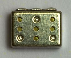
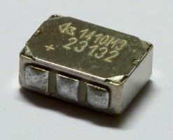
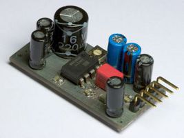
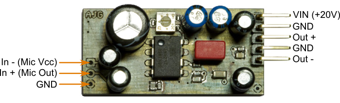
The preamplifier is designed to be used with a miniature electret condenser microphone capsule, in particular the Knowles EK-23132 omnidirectional capsule. The capsule and preamplifier board are shown below. The aim was to produce a small board to simplify the creation of a microphone array. The final size is 42mm x 20mm x 16mm. It is powered from a single +20V supply and has a balanced output that can drive a long cable run at line level.
|
|
|
The left hand image below shows the capsule's internal wiring. The FET and resistor form a potential divider from which the output is derived. As the microphone's diaphragm moves, the FET's resistance changes therefore so does the output. It is also possible to create a balanced output by connecting an external resistor as shown in the right hand figure below. This additional resistor should have the same value as the capsule's internal resistor. This configuration should provide improved power supply noise rejection as any supply noise will be common to both the outputs. Note that rejection is not 100% as due to the potential divider, different proportions of supply noise will transfer to the outputs.
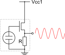
Standard wiring configuration |
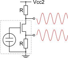
Balanced wiring configuration |
With microphone array beamforming in mind, the amplifier's balanced line level output works well with the Alesis HD-24 and the Focusrite Saffire Pro 10 I/O.
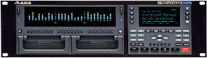
Alesis ADAT HD-24 |
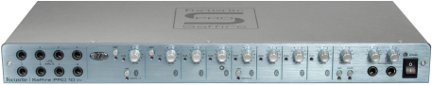
Focusrite Saffire Pro 10 I/O |
Design and Schematics
The full preamplifier schematic can be downloaded using the links below.
Input Stage
The main amplification stage is performed using a INA217, a high-quality low-noise, low-distortion audio instrumentation amplifier. An active servo circuit based on an OPA137 is used to bias the amplifier's output to midway between the supply rails.
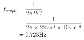
Input coupling high pass filter |
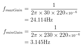
Gain setting high pass filter |
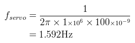
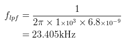
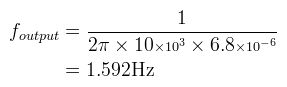
Servo low pass filter |
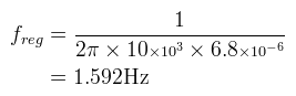
Note:The 1kΩ resistor and 150pF capacitor values for the low pass input filter stage were determine through trial and error.
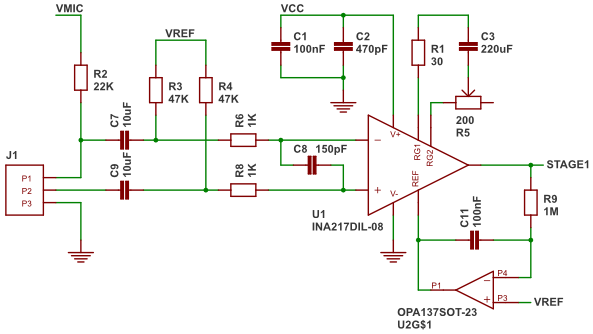
Stage 1 - Main Amplification Stage
Output Stage
The second stage is a low pass filter followed by a line driver. The output stage uses a DRV135 audio balanced line driver. The output can be configured in one of two modes. Either the output can be taken directly from the DRV135, or via the output DC blocking caps. As can be seen on the PCB below, the selection is made with a simple solder bridge.
Mid stage low pass filter |
Output AC couple high pass filter (10kΩ load assumed) |
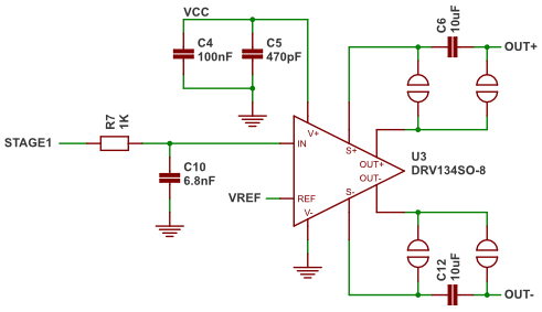
Stage 2 - Balanced Cable Driver
Regulators
The preamplifier uses two LDO voltage regulators. The main board voltage is 15V, generated by a 78L15. The microphone capsule has its own low noise regulator a LP2985-50, with a 5.0V output. To help remove noise from the microphone supply, a low pass filter is used between the main board supply and the microphone supply regulator.
Microphone supply regulator low pass filter
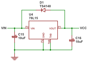
Main Supply Regulator |
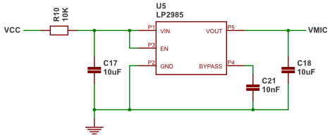
Microphone Supply Regulator |
Reference Voltage
As the preamplifier operates using a single supply voltage, a mid-supply reference voltage is required for biasing the audio signal. This is generated using a TLE2426, a precision rail splitter. The 8pin version with extra noise reduction is used.
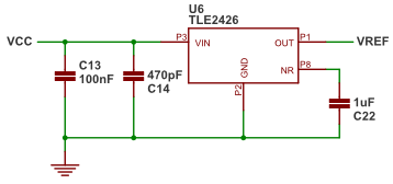
Mid Supply Reference Voltage
Misc
The final parts are the board connector, a ground probe connection point and some decouple/bypass capacitors for the OPA137.
Connectors and OPA137 Bypass/Decouple Capacitors
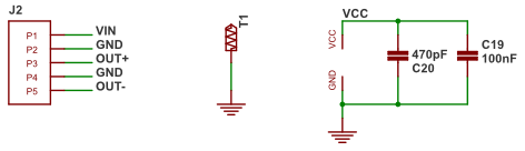
Connections
The board's connections are shown below.
Preamplifier board connections
Component Listing
Below is a list of the parts required to build the preamplifier. All the parts are available from Farnell.
| ICs | ||||
| PCB Number | Value | Farnell Code | Spec | Notes |
|---|---|---|---|---|
| U1 | INA217 | 121-2423 | Instrumentation amplifier, PDIP8 | Stage 1 amplifier. Differential input |
| U2 | OPA137 | 156-4895 | FET Input op-amp | Active servo biasing |
| U3 | DRV135 | 121-2389 | Audio op-amp | Stage 2 amplifier. Differential output |
| U4 | 78L15 | 164-8661 | 15.0V LDO Regulator | Main supply regulator |
| U5 | LP2985-50 | 977-8292 | 5.0V LDO regulator | Microphone supply regulator |
| U6 | TLE2426 | 845-4809 | Virtual Ground Reference | Mid supply reference |
| Capacitors | ||||
| PCB Number | Value | Farnell Code | Spec | Notes |
| C8 | 150pF | 969-5133 | PPS 0803, 50V | Input stage low pass filter |
| C2, C5, C14, C20 | 470pF | 880-9904 | Ceramic 0603, C0G, 50V | IC bypass/decouple capacitors |
| C10 | 6.8nF | 100-5989 | Polypropylene, 63V | Mid-stage low pass filter |
| C21 | 10nF | 175-9022 | Ceramic 0603, X7R, 25V | Microphone regulator bypass cap |
| C1, C4, C11, C13, C19 | 100nF | 940-6387 | Ceramic 0805, X7R, 50V | IC bypass/decouple capacitors and servo biasing filter |
| C22 | 1uF | 175-9454 | Ceramic 1206, X7R, 50V | Reference IC noise reduction |
| C17, C18 | 10uF | 161-1967 | Ceramic 1206, Y5V, 35V | Mic supply Regulator |
| C15, C16 | 10uF, | 286-606 | Aluminium Electrolytic, 63V, ±20% | Main board supply Regulator |
| C6, C7, C9, C12 | 10uF | 123-6669 | Aluminium Electrolytic, Non-Polar, 35V, ±20% | Input and output AC coupling. |
| C3 | 220uF | 123-6663 | Aluminium Electrolytic, Non-Polar, 16V, ±20% | Gain stage DC decouple. |
| Resistors | ||||
| PCB Number | Value | Farnell Code | Spec | Notes |
| R1 | 30Ω | 933-3029 | 0805, 0.1W, 1% | Max gain limiting resistor |
| R5 | 200Ω | 168-9908 | 4mm Trimmer | Gain control |
| R6, R7, R8 | 1KΩ | 146-9740 | 0603, 0.1W, 1% | Input and mid stage low pass filters |
| R10 | 10KΩ | 146-9856 | 0805, 0.125W, 1% | Mic Regulator low pass filter |
| R2 | 22KΩ | 146-9896 | 0805, 0.125W, 1% | Microphone capsule series resistor |
| R3, R4 | 47KΩ | 169-2459 | 0603, 0.063W, 1% | Input stage biasing |
| R9 | 1MΩ | 933-2413 | 0805, 0.1W, 1% | Servo biasing filter |
| Discrete | ||||
| PCB Number | Value | Farnell Code | Spec | Notes |
| D1 | TD4148 | 815-0206 | 0805, 0.5A | Main supply regulator protection |
| M1 | EK23132 | 130-0693 | Omnidirectional electret microphone capsule | |
| Connectors & Switches | ||||
| PCB Number | Value | Farnell Code | Spec | Notes |
| J1 | 1x3 | 341-8297 | Straight 3 way header, 0.1" pitch | Input Connector |
| J2 | 1x5 | 159-3429 | Right-angle 5 way header, 0.1" pitch | Supply and output connector |
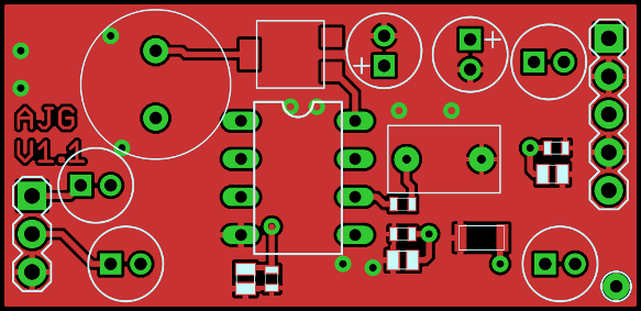
Printed Circuit Board
The full preamplifier board layout can be downloaded using the link below.

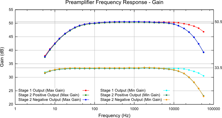
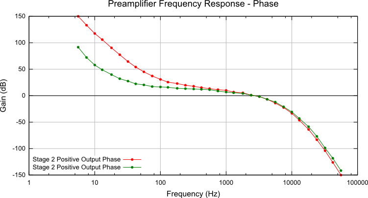
Frequency Response
The setup shown below was used to analyse the preamplifier's performance.
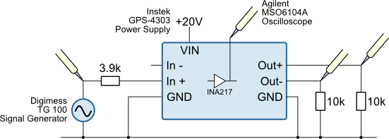
Below are plots of the gain and phase response of the preamplifier.