


BioNode System
The BioNode system is a multicellular architecture that uses a novel communication system based on biological endocrinology. I built the system as part of my PhD research.
Overview
The aim of the BioNode system was to create a novel fault tolerant data processing system. Biology was used a source of inspiration for achieving fault tolerance. The completed system is shown in the image below. It contains 30 networked processing elements. The network is structured in a square grid, with each cell having connections to its 8 nearest neighbours. This topology explains the toroidal shape.
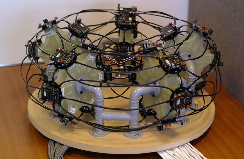
The BioNode System
Two main aspects of biology are used to achieve fault tolerance. First, cells are grouped together into organs that operate together to provide a single function. Second, a fault tolerant communication system based on endocrinology is used to allow organs to communicate. The result is a system that can tolerate the loss of both cell and communication packets between cells without overall system failure.
Endocrinology
Three types of communication systems can be found in biological systems. This are mainly differentiated by the distance that the communication system operates over. The three types are listed below.
- Endocrine - Long distance
- Paracrine - Shorter distance, neighbouring cells
- Autocrine - Shortest distance, communication with self
These three communication modes are depicted below.
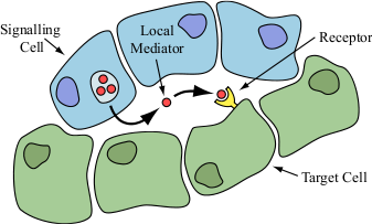
Paracrine Signalling |
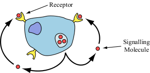
Autocrine Signalling |
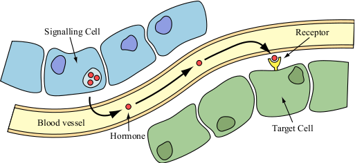
Endocrine Signalling
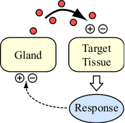
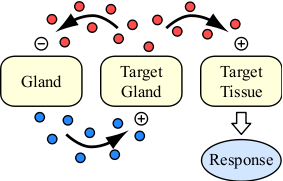
Endocrine Based Control
Endocrine signalling provides a system which allows the body to maintain control over. In general this operate in a similarly to a classic negative feedback controller system. The images below show two such control systems. In these case, the control is mediated by endocrine hormone messages.
The BioNode System |
The BioNode System |
Data Processing
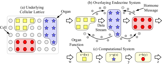
The figure below describes how the BioNode system operates using the biologically inspired techniques to perform data processing. The first stage is splitting the require system operation into organs, in this case there are three indicated by the square, stars and hexagons. The round cells are dormant spare cells, these can be brought into action to replace a failed cell.
Data flows from one organ to the next in waves of endocrine-like signals. For example, the 'squares' organ releases messages that stimulate the 'stars' organ into action. Once stimulated this organ releases its own messages that both inhibit the previous organ and stimulate the next.
The BioNode System
As messages are sent in waves, if a few are lost or corrupted, then the overall activation of inhibition signal still gets though. Also, as organs are constructed from multiple co-operative cells, it is possible to remove and replace cells with loss of organ operation.
The BioNode System Hardware
Each BioNode contains a Xilinx Spartan FPGA and an Atmel AVR.
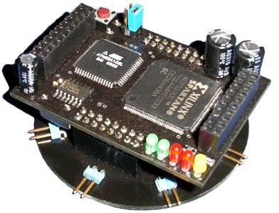
The BioNode |
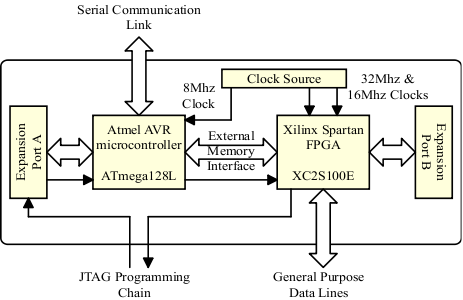
The main BioNode components |
Support Hardware
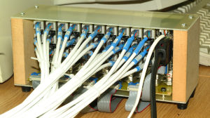
The JTAG multiplexer
The BioNode's microprocessor and FPGA are programmed using a JTAG chain. In order to configure each of the system's nodes in isolation, individual JTAG access to each BioNode is required. This photo shows the JTAG multiplexer that allows you to select the different nodes.
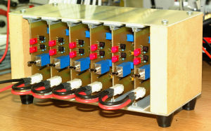
Power regulator boards
This photo shows the set of regulators that power the BioNodes. Each regulator board powers 5 nodes.
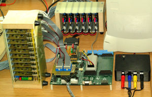
The complete support system
The complete set of support hardware. The multiplexer boards are connected to a FPGA development board. This also multiplexes the 30 serial data lines connected to the BioNodes.
A schematic of the support system and how it connects to the BioNodes is shown below.
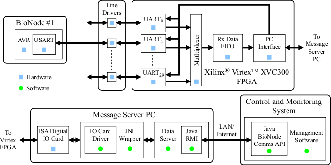
The complete support system
