


I²C Controller
The I²C standard is used in a wide variety of electronic components. Everything from microcontrollers to digital compasses make use of the standard for inter-device communication.
The VHDL modules described here can be used to master an I²C bus. The Simple Master Module provides a simple method of interfacing a microcontroller to a I²C bus, whereas the Controller Module is programmable and allows complex sequences of basic I²C communication operations to be offloaded from the main host processor.
System Overview
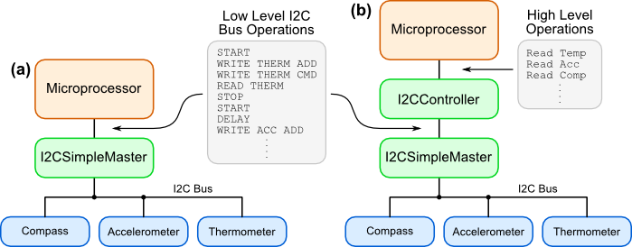
The Simple Master Module performs the basic I²C
operations: START, STOP, RESTART, WRITE,
READ_ACK and READ_NACK. This module can be used on its own and can easily
be interfaced to a microcontroller, see (a) in figure below. The second module is a basic controller
that can be programmed to perform whole sequences of I²C communication operations. The idea is to
offload the task of low-level bus control from the host processor, see (b) in the figure below. For
example, the controller could be programmed to periodically read values from a thermometer, compass
and accelerometer without any other control required from the host processor, which then only has to read
off the sensor data values once collected.
The I²C Controller Module makes it possible to offload a lot of low level I²C operations from the host processor
If you have a very complex I²C slave peripheral, then direct control available with the Simple Master Module is probably best way to go. However, for most other tasks, you can free up valuable microprocessor cycles by making use of the Controller Module.
The VHDL for the modules is linked to below.
The Simple Master Module
The Simple Master performs the basic I²C Master operations, these are shown in the figure below. Full communication with a peripheral is achieved by chaining together a set of these basic operations. Internal to the Simple Master Module, each operation is split into groups of 4 stages (labelled A to D).
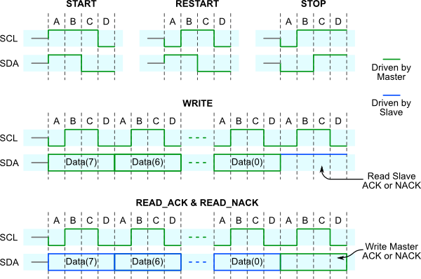
I²C operations are constructed from groups of 4 stages
The ports of the VHDL module are shown in the entity description below. Operation of the module is very simple.
- The required operation is applied to the
operationinput, as well as data todataMstr2Busif the operation is aI2C_WRITE_DATA. - The operation is started by a pulsing enable.
- When the operation is complete the
donesignal will go high (it remains high until the next enable pulse). - If the operation was a
I2C_WRITE_DATA, the acknowledge level from the slave is available onslaveAck. If the operation was aI2C_READ_DATA_ACKorI2C_READ_DATA_NACKthe read data is available ondataBus2Mstr.
I2CSimpleMaster.vhdlentity I2CSimpleMaster is generic( TICK_NUM : integer); port ( clk : in std_logic; reset : in std_logic; sclOut : out std_logic; sdaIn : in std_logic; sdaOut : out std_logic; enable : in std_logic; -- Start an operation operation : in I2C_MASTER_OP; -- Operation required done : out std_logic; -- Indicates Master is done (not busy) dataMstr2Bus : in std_logic_vector(7 downto 0); -- Data from Master to I²C Bus dataBus2Mstr : out std_logic_vector(7 downto 0); -- Data from I²C Bus (slave) to Master slaveAck : out std_logic); -- Acknowledge level from slave (on write) end I2CSimpleMaster;
The I2C_MASTER_OP type is declared in I2CPkg.vhdl. The valid values are shown in the excerpt below. A
function called to_I2C_MASTER_OP is also available for converting a std_logic_vector into a I2C_MASTER_OP, handy if
interfacing to a microcontroller data bus.
I2CPkg.vhdltype I2C_MASTER_OP is ( I2C_START, I2C_RESTART, I2C_STOP, I2C_WRITE_DATA, I2C_READ_DATA_ACK, I2C_READ_DATA_NACK); function to_I2C_MASTER_OP( value : std_logic_vector(2 downto 0) ) return I2C_MASTER_OP is variable result : I2C_MASTER_OP; begin case value is when b"000" => result := I2C_START; -- 0 when b"001" => result := I2C_RESTART; -- 1 when b"010" => result := I2C_STOP; -- 2 when b"011" => result := I2C_WRITE_DATA; -- 3 when b"100" => result := I2C_READ_DATA_ACK; -- 4 when others => result := I2C_READ_DATA_NACK; -- 5 end case; return result; end function to_I2C_MASTER_OP;
The waveforms below show the Simple Master in operation. Note that this simulation does not include any slave response. So, the slave acknowledge and read data is always read as logic 1.
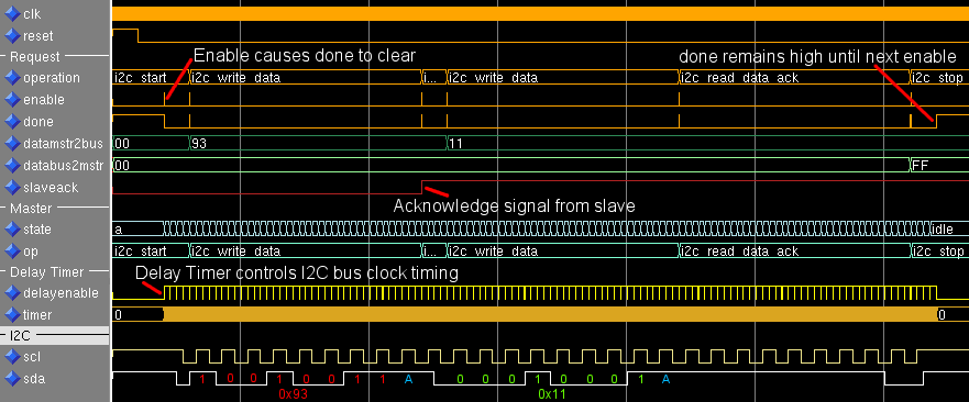
Simple Master Module waveforms showing a basic I²C communication
Setting the Bus Clock Speed
The TICK_NUM generic sets the frequency of the I²C bus clock signal (scl) driven by the master.
TICKNUM = (fClk / (4 * speed)) - 2
where,  fClk:  Frequency of clk input (Hz)
        speed: I²C Bus speed (bits/second
Here are some examples:
fClk:  10 MHz Clock
speed: 10 kbit/s (Low-speed mode)
TICK_NUM = (10000000 / (4 * 10000)) - 2
         = 248

fClk:  50 MHz Clock
speed: 100 kbit/s (Standard mode)
TICK_NUM = (50000000 / (4 * 100000)) - 2
         = 123
I²C Bus Signal Connections
The serial data signals (sdaIn & sdaOut) and clock signal
(sclIn) from the Simple Master Module need correct interfacing to the open-drain I²C
bus signals. The snippet of VHDL shows how to achieve this.
-- Create Open-Drain I²C IO
sdaIn <= sda;
sda <= '0' when sdaOut='0' else 'Z';
scl <= '0' when sclOut='0' else 'Z';
This should create a circuit like the one shown below.
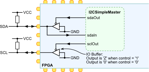
Adding tri-state buffers to I²C signals for correct open drain operation
NOTE: The Simple Master Module does not respect clock stretching, a technique used by slaves to pause the master. In most cases this should not be a problem. However, keep it in mind if communication fails occasionally.
The Controller Module
The Controller Module provides a more advanced form of I²C bus control. It allows sequences of the basic I²C to be chained together with basic flow control and a register file for holding temporary values. The image below shows the structure of the Controller Module.
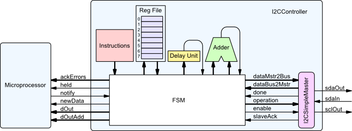
A basic block diagram of the I²C Controller Module
The table below describes the available instructions. It's worth mentioning at this stage that the controller design is quite simple and so is easily adjusted to suite other requirements.
| Instruction | Argument, 3 bits | Data, 8 bits | Description |
|---|---|---|---|
I2C_WRITE_REG |
Register Number | - | Write the data value held in the specified register to the I²C bus. |
I2C_WRITE_IMM |
- | Immediate Value | Write the immediate value to the I²C bus. |
I2C_READ_DATA_ACK |
Register Number | - | Read data from the I²C bus and load into designated register. Can either ACK or NACK the slave. |
LOAD |
Register Number | Immediate Value | Load the immediate value into the selected register. |
ADD |
Register Number | Immediate Value | Add the immediate value to a value held in the selected register. Subtraction is achieved by adding (256 - immediate value). |
COMP |
Register number | Immediate value | Compare the immediate value with the data value held in the selected register. The result can be used for conditional jumps. |
OUTPUT |
Register Number | Address | Output the value held in the selected register to dOut. Output the address value to dOutAdd. |
DELAY |
Upper 3 bits of delay count | Lower 8 bits of delay count | Delay the controller for the selected number of milliseconds. |
JUMP |
Condition | Instruction Address | Jump to instruction. If condition is EQUAL, only jump if COMP matched. If condition is NOT_EQUAL, only jump if COMP did not match. If condition is ALWAY, always jump. |
HOLD |
- | - | Hold the controller until a the notify input is asserted. Whilst held, the held output is high |
The VHDL module entity is shown below. Like the Simple Master, it has a very simple interface.
The CLK_FREQ generic is used to calibrate the DELAY instruction. Set it to
the frequency of the clk signal in Hertz. The TICK_NUM generic is set in
the same way as described above. The important part is the PROGRAM generic that specifies what
the controller does.
I2CController.vhdlentity I2CController is generic (CLK_FREQ : integer; I2C_TICK_NUM : integer; PROGRAM : I2C_CONTROLLER_PROG); port ( clk : in std_logic; reset : in std_logic; sclOut : out std_logic; sdaIn : in std_logic; sdaOut : out std_logic; held : out std_logic; notify : in std_logic; dOutAdd : out std_logic_vector(3 downto 0); dOut : out std_logic_vector(7 downto 0); newData : out std_logic; ackErrors : out std_logic_vector(7 downto 0)); end I2CController;
Example Program
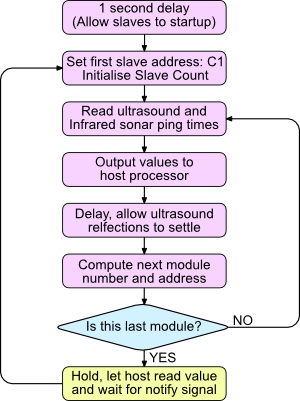
Flow chart of example program
The controller program is specified as a generic when a controller module is instantiation. An example program is shown below. It is used to read ultrasonic and infrared data from 6 range finding modules. A flow chart for the program is shown to the right.
Operation is quite simple. A module counter variable and address variable are first initialised.
Then, each module is queried in turn. The counter variable is incremented after each query and checked to see if
all 6 modules have been read. The HOLD instruction is then used to tell the host microprocessor that
data is ready. When the notify input is asserted, reading loop is restarted.
Hold and Notify
This is a very basic interrupt system for the controller. The HOLD instruction
causes the controller to pause and assert the held signal. It will wait at this
instruction until the notify input is asserted. The idea is to connect the
held signal to an interrupt input of the host microprocessor, such that the I²C
Controller Module can indicate that data is ready for reading.
constant I2C_PROG : I2C_CONTROLLER_PROG(0 to 17) := (
 (op => DELAY,              arg => b"011",    data => x"E8"),   -- 0:  Startup Delay (1s)

 (op => LOAD,               arg => R0,        data => x"00"),   -- 1:  Initialise Module Number
 (op => LOAD,               arg => R1,        data => x"C1"),   -- 2:  Initialise Address

 (op => I2C_START,          arg => VOID,      data => x"00"),   -- 3:  Start
 (op => I2C_WRITE_REG,      arg => R1,        data => x"00"),   -- 4:   Control Byte (Read)
 (op => I2C_READ_DATA_ACK,  arg => R2,        data => x"00"),   -- 5:   Read ultrasound range
 (op => I2C_READ_DATA_NACK, arg => R3,        data => x"00"),   -- 6:   Read infrared range
 (op => I2C_STOP,           arg => VOID,      data => x"00"),   -- 7:  Stop

 (op => OUTPUT,             arg => R0,        data => x"00"),   -- 8:  Output Module Number
 (op => OUTPUT,             arg => R2,        data => x"01"),   -- 9:  Output ultrasound
 (op => OUTPUT,             arg => R3,        data => x"02"),   -- 10: Output infrared range

 (op => DELAY,              arg => b"000",    data => x"18"),   -- 11: Delay (Approx 30 ms between pings)

 (op => ADD,                arg => R0,        data => x"01"),   -- 12: Compute next module number
 (op => ADD,                arg => R1,        data => x"02"),   -- 13: Compute next device address

 (op => COMP,               arg => R0,        data => x"06"),   -- 14: Test Module Number
 (op => JUMP,               arg => NOT_EQUAL, data => addr(3)), -- 15: Jump to next sonar read

 (op => HOLD,               arg => VOID,      data => x"00"),   -- 16: Wait for signal from host
 (op => JUMP,               arg => ALWAYS,    data => addr(1))  -- 17: Jump to initialise Address
);
