


Switch Debouncing
Switch debouncing is one of those things you generally have to live with when playing with switches and digital circuits. If you want to input a manual switch signal into a digital circuit you'll need to debounce the signal so a single press doesn't appear like multiple presses.
There are already a considerable number of pages on this topic. So here's another!
What is Switch Bounce?
The left-hand image below shows a simple push switch with a pull-up
resistor. The right hand image shows the trace at the output terminal,
Vout, when the switch is pressed. As can be seen, pressing the switch
does not provide a clean edge. If this signal was used as an input to a digital
counter, for example, you'd get multiple counts rather than the expected single
count.
Note that the same can also occur on the release fo a switch.
The problem is that the contacts within the switch don't make contact cleanly, but actually slightly 'bounce'. The bounce is quite slow, so you can recreate the trace, and the problem quite easily.
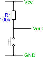
Simple switch pull-up circuit |
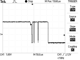
Switch bounce produced on switch press |
In the switch waveform the bouncing lasts for about 150us.
A Switch Debouncer Circuit
There are many different approaches to cleaning up switch bounce. Below is a debouncing circuit. The basic idea is to use a capacitor to filter out any quick changes in the switch signal.
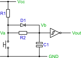
A Switch debouncing circuit
The circuit's operation can be explained by looking at the equivalent circuits formed in the two switch states, open and closed.
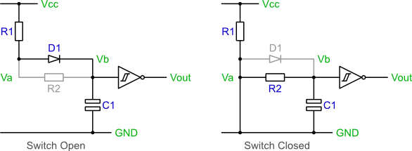
Debouncing circuit in switch open and closed states
Starting with the switch open.
- The capacitor
C1will charge viaR1andD1. - In time,
C1will charge andVbwill reach within 0.7V ofVcc. - Therefore the output of the inverting Schmitt trigger will be a logic 0.
Now close the switch
- The capacitor will discharge via
R2. - In time,
C1will discharge andVbwill reach 0V. - Therefore the output of the inverting Schmitt trigger will be a logic 1.
But what about bounce conditions? If bounce occurs and there are short
periods of switch closure or opening, the capacitor will stop the voltage at
Vb immediately reaching Vcc or GND. Although,
bouncing will cause slight charging and discharging of the capacitor, the
hysteresis of the Schmitt trigger input will stop the output from
switching.
What about the diode? Well the resistor R2 is required as a
discharge path for the capacitor, without it, C1 will be shorted when
the switch is closed. Without the diode, D1, both R1
and R2 would form the capacitor charge path when the switch is open.
The combination of R1 and R2 would increase the capacitor
charge time, slowing down the circuit. So, can't you just make R1
smaller? Ideally no, when the switch is closed, R1 is connected across
the supply rails, so too small a resistor value would lead to unwanted wasted
current.
Software Debounce
Debouncing a switch in software is very simple. The basic idea is to sample the switch signal at a regular interval and filter out any glitches. There are a couple of approaches to achieving this listed below. Both approaches assume a switch circuit like that shown in the explanation of switch bounce: a simple push switch with a pull-up resistor.
Approach 1
The first approach uses a counter to time how long the switch signal has been low. If the signal has been low continuously for a set amount of time, then it is considered pressed and stable.
 1 Setup a counter variable, initialise to zero.
 2 Setup a regular sampling event, perhaps using a timer. Use a period of about 1ms.

 3 On a sample event:
 4   if switch signal is high then
 5     Reset the counter varaible to zero
 6     Set internal switch state to released
 7   else
 8     Increment the counter variable to a maximum of 10
 9   end if
10   if counter=10 then
11     Set internal switch state to pressed
12   end if
Approach 2
The second approach is similar to the first, but uses a shift register instead of a counter. The algorithm assumes an unsigned 8bit register value, such as that found it 8-bit microcontrollers.
 1 Setup a variable to act as a shift register, initialise it to xFF.
 2 Setup a regular sampling event, perhaps using a timer. Use a period of about 1ms.

 3 On a sample event:
 4   Shift the variable towards the most significant bit
 5   Set the least significant bit to the current switch value
 6   if shift register val=0 then
 7     Set internal switch state to pressed
 8   else
 9     Set internal switch state to released
10   end if
Digital Switch Debouncing
Digital debouncing is achieved in basically the same way as the software approaches described above. The circuit shown below is a basic switch debouncer. Although it looks a lot just to debounce a switch signal, it is in fact very simple.
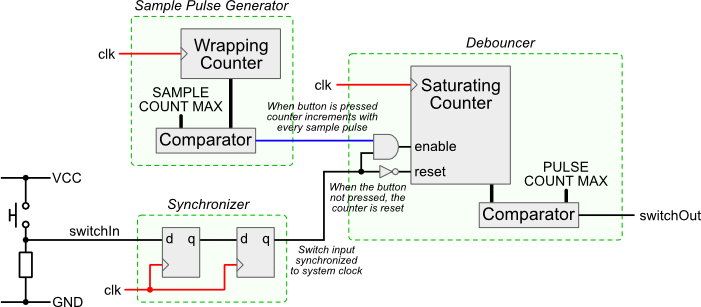
Example digital debouncing
The three main parts are:
- Sample Pulse Generator - A counter that increments every clock edge. When the maximum is reached a sample pulse is generated and the count value resets to zero. The sample pulse is used to sample the switch input.
- Synchroniser - The Synchroniser makes sure the switch signal is synchronised with the system clock, the double flip-flop minimises the chance of metastability.
- Debouncer - A counter that is incremented every sample pulse whilst the switch is pressed. When the switch is not pressed the counter is reset to zero. If the counter is at its maximum, the debouncer output is high, otherwise it is low.
The operation of the circuit is illustrated in the set of waveforms below. The most interesting part is the debouncer counter waveform. This can be seen to count up when the switch input is high. During periods of switch bounce the counter keeps getting reset to zero, it only reaches its maximum value once the switch input has stabilised.
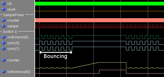
Simulation of the digital debouncer circuit
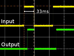
Example button press and release timing
The timing of this circuit needs some consideration. The maximum values of the two counters need to be set depending upon a) the system clock frequency, b) the shortest expected press time and c) the longest bounce time.
The two traces to the right were generated by pressing a switch as fast as possible. So, the 33ms is a good representation of a minimum switch pressed time.
The two circuit parameters are set as follows:
SAMPLE COUNT MAX - Set this value to give a sensible switch sampling rate, something around a pulse every 500 us is fine. Higher values mean the pulse counter needs to be bigger, too low and you'll miss short switch presses. Given a system clock frequency of 50MHz:
SAMPLE COUNT MAX = (Clock Frequency / 2000) - 1
                 = (50000000 / 2000) - 1 = 24999
PULSE COUNT MAX - Set this high enough that bouncing regions are ignored, but low enough that the shortest button press will still cause the counter to saturate at this value.
Given a pulse timing of 500 us a good value is 20, this equates to 10 ms. Bounces shorter than 10 ms are ignored and switch presses longer than this are detected.
A VHDL module for switch debouncing using this approach is linked to below.
The VHDL entity description is shown below. As the two generics suggest, the debouncing timing is automatically set based
on the CLK_FREQ value. Also, the module will debounce multiple switches.
SwitchDebouncer.vhdlentity SwitchDebouncer is generic (CLK_FREQ : positive; NUM_SWITCHES : positive); port ( clk : in std_logic; reset : in std_logic; switchesIn : in std_logic_vector(NUM_SWITCHES-1 downto 0); switchesOut : out std_logic_vector(NUM_SWITCHES-1 downto 0)); end SwitchDebouncer;
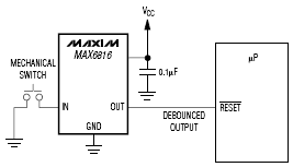
Switch Debouncing ICs
For such a common problem, you'd think there would be a plethora of ICs for performing switch debounce. However, there don't seem to be that many. Below is a list of those I've found so far. Unfortunately, one is not easily acquired, the other is expensive.
|
Number: MAX6816, MAX6817, MAX6818 Manufacturer: Maxim-Dallas Web Page: http://www.maxim-ic.com/quick_view2.cfm/qv_pk/1896 Notes: Apart from Maxim's sample service, I've not found anyone who sells these parts in small quantities. |
|
Number: MC14490 Manufacturer: ON Semiconductor Web Page: http://www.onsemi.com/PowerSolutions/product.do?id=MC14490 Notes: Farnell sell these, but they seem very over priced. |
