


Wheel Encoder
Detecting wheel rotation is common task in robotics. This pages describes one approach based on optical sensors that can detect both the amount and direction of wheel rotation.
Introduction
The photos below show a setup for detecting the direction and amount of a wheel's rotation. The two main parts are the encoder wheel and the opto-sensor. The encoder wheel has evenly spaced holes around the diameter and in this case is made from etched brass sheet. The opto-sensor is a dual channel TCUT1200.
As the encoder wheel passes over the opto-sensor, the transitions from a gap to a non-gap are detected. The signals from the sensor can be decoded to produce a count of the number of transitions. The count increments for one direction and decrements for the other.
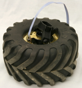
Wheel with encoder |
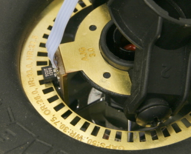
Sensor engaged with encoder wheel |
The sensor used is a Vishay dual channel opto sensor. It has a infrared LED that shines on to two photo transistors. This particular sensor has two great advantage. First, having two channels makes it possible to detect the direction of rotation as well as the amount. Second, the face-to-face construction of LED and sensors provides more robust detection than the reflective types.

Vishay dual channel opto-sensor |
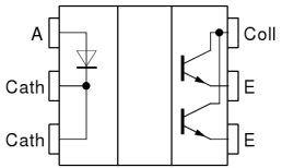
Internal circuit of the TCUT1200 |
The simple circuit required for the wiring the sensor is shown below. The outputs can then be connected to a microcontroller or an FPGA.
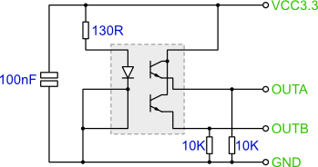
The sensor circuit
Encoder Wheels
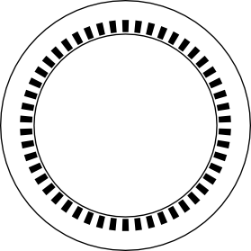
An example encoder wheel
An example encoder wheel is shown to the right. This was generated using the script linked to below. The script is written in PHP and generates a SVG file as the output. Inkscape is a very good option for printing out or converting the resulting SVG.
You need to set 5 variables in the script to specify the number of gaps and the dimensions of the wheel. The image below illustrates the meaning of the dimension variables.
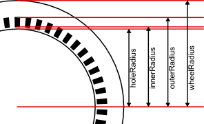
Wheel generator script variables
The gaps size needs to be set so that during rotation, there is a point where both detectors are covered and also when they are both uncovered.
Quadrature Decoding
During wheel rotation the output from the opto-sensors will reflect four stages. These stages are reflected in the image below.
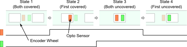
The four states of the sensor during wheel rotation
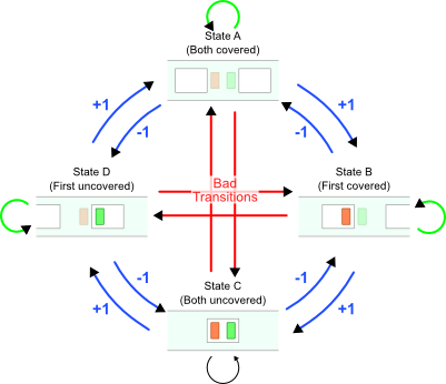
Movement decoder state machine
The state machine shown to the left describes the possible transitions that may occur during rotation. By detecting these transitions you can keep track of wheel rotation.
Transitions can be split into 3 groups:
- Group one just represent 'no change in state', these are the small loops around the edges of the state diagram shown in green.
- The next group are the transitions that should not occur, these are the four red transitions in the centre marked 'Bad Transitions'. Although, it is not physically possible for these transitions to occur, if movement is too quick, or the system detecting transitions too slow, it is possible for these transitions to 'seem' to occur'.
- The final group, marked in blue are the important ones.
A counter can be used to keep track of the rotation. When the wheel rotates, each state transition will cause the counter to either increment or decrement depending on direction.
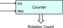
State transitions controlling a counter for measuring wheel rotation
Below is a oscilloscope screen grab of the two sensor outputs. The time between transitions in this case is about 2.5ms - 3ms, which was for a fairly fast speed of wheel rotation.
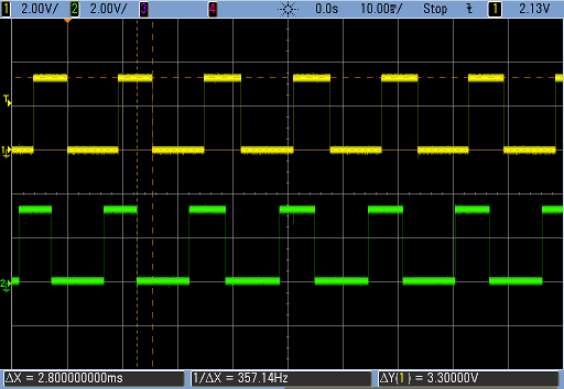
Scope trace of sensor outputs
VHDL Module
A VHDL module that decodes the quadrature signals from the sensors and outputs a counter value is linked to below. The system is quite simple. The sensor signals are first buffered to synchronize to the FPGA clock, then a voter is used on each input in order to remove any glitches. The sensor values are then compared with a delayed version in order to detect the transitions.
WheelDecoder.vhdlentity WheelDecoder is generic (CLK_FREQ : in integer); port ( clk : in std_logic; reset : in std_logic; sensorA : in std_logic; sensorB : in std_logic; countOut : out std_logic_vector(15 downto 0)); end WheelDecoder;
The VHDL module follows the same labelling as the state machine shown above. So it should be
quite straight forward to follow. A very simple testbench and ModelSim do script is
also in the archive, plus a few more bits if you want to implement it on an FPGA.
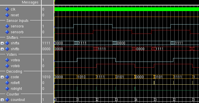
ModelSim waveform
