


Sonar
Get the Flash Player to see this player.
Sonar systems are a key part of mobile robotics platforms. Collision avoidance systems need a method of detecting obstacles and sonar modules can provide this function. This page describes a sonar module that includes both a ultrasonic and infrared sonar modules. A light level sensor is also included.
Introduction
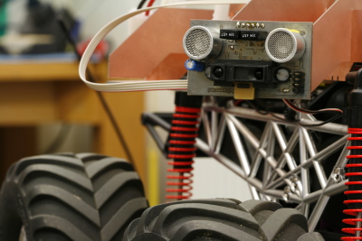
Sonar Modules mounted on robot |
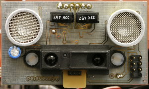
Ultrasound and infrared sonar |
Ultrasound Sonar
The principle of sonar echo location is very simple. A sound pulse is transmitted and the time taken for a reflection to return give an indication of the distance to the reflecting surface. In this case 40kHz ultrasound is used.
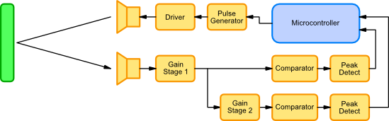
Ultrasound Sonar System
Waveforms
The waveforms below show the how the ultrasonic circuit operates in different circumstances.
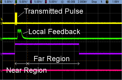
No Reflection
The first set of waveforms shows the situation when there are no obstacles. The yellow trace (1) shows the transmitted ping, a short burst of 40KHz.
The green trace (2) shows the output of the second receiver stage. A received pulse is visible, but this is not a true reflection, but the transmitted signal being directly received. Because of the high gain, this signal will be picked up, but must be ignored.
The purple trace (3) is the judged distance. The signal is set high when a pulse is transmitted and set low when a reflection is received. In this case, as no reflection has been received, the signal stays high until the timer reaches its maximum.
Note the two regions. The near region only uses the first lower gain stage to detect reflections. The far region uses both receiver stages.
Far Obstacle
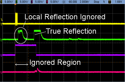
When a distant object is detected, the second stage trace now shows a true reflection pulse as well as the local feedback. The purple trace shows the judged distance of the obstacle, the feedback pulse has been ignored.
Note that there is a slight pulse on the first stage trace (pink). The obstacle is just close enough to cause the first lower gain stage to detect the obstacle.
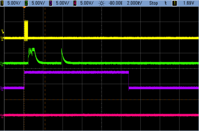
Near Obstacle
For detecting near obstacles, the lower gain first receiver stage is used. This gets around the problem of the local feedback signal obscuring any true reflections.
The pink trace shows a the true reflection, the green trace also shows lots of reflection, but the local feedback gets in the way.
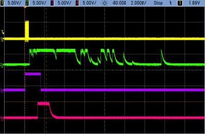
Spike Removal
To make sure that noise does not cause false obstacle detection, any received short spikes must be ignored. This set of waveforms show that the short spike in the green trace is ignored.
Infrared Sonar
Schematics and PCB
Microcontroller Code
